Wall-driven channel flow#
In this tutorial we will consider a wall-driven channel flow as described by Chnafa [Chn14]. The problem is one of the simplest examples of a flow in a time-dependent domain flow of a Newtonian fluid in a long, straight, two-dimensional channel subjected to a time varying height. The problem is implemented in the file MovingWall.py .
Problem description#
In this problem the flow is purely wall driven, and is induced by a moving wall at \(y = h(t)\) on the top of the channel which remains parallel to the x-axis, defined as:
where \(\omega\) is the pulsation of the movement, \(h_0\) is the mean distance between the symmetry axis \((y = 0)\) and the moving wall, and \(\epsilon\) is the amplitude of the oscillations. Note that for small values of \(\epsilon\) the problem has a pseudo-analytical solution, which can be used to validate the numerical solution [Nic02]. Hence, the flow must be considered at small Reynolds number in order to be in close agreement with the analytical solution. Here, the Reynolds number is set between 0 and 0.4, with the default parameters of \(\epsilon = 0.05, \omega = 2\pi\) rad s\(^{-1}\), \(h_0 = 0.001\) m, and \(\nu = 8\cdot 10^{-1}\) m\(^2\, \)s\(^{-1}\). The velocity is assigned vertically at the wall on the top of the domain using the derivative \(h'(t)\), while zero pressure is prescribed at the plane at \(x = 25h_0\). A free-slip condition is applied at the bottom of the domain (\(y=0\)), and we impose a symmetry condition for the wall at \(x=0\).
Simulation in OasisMove#
To run the wall-driven channel flow problem for \(T=1\) seconds with the default parameters in OasisMove you can run the following command:
$ oasismove NSfracStepMove problem=MovingWall
and the simulation will start. The default time step size is set to \(\Delta t=0.005\), thus a full simulation performs 200 time steps, and should be complete within less than a minute.
Results#
When the simulation is finished, there will be a folder named results_moving_wall, which contains the velocity and
pressure solution in .xdmf format. These solution files can be visualized in ParaView or
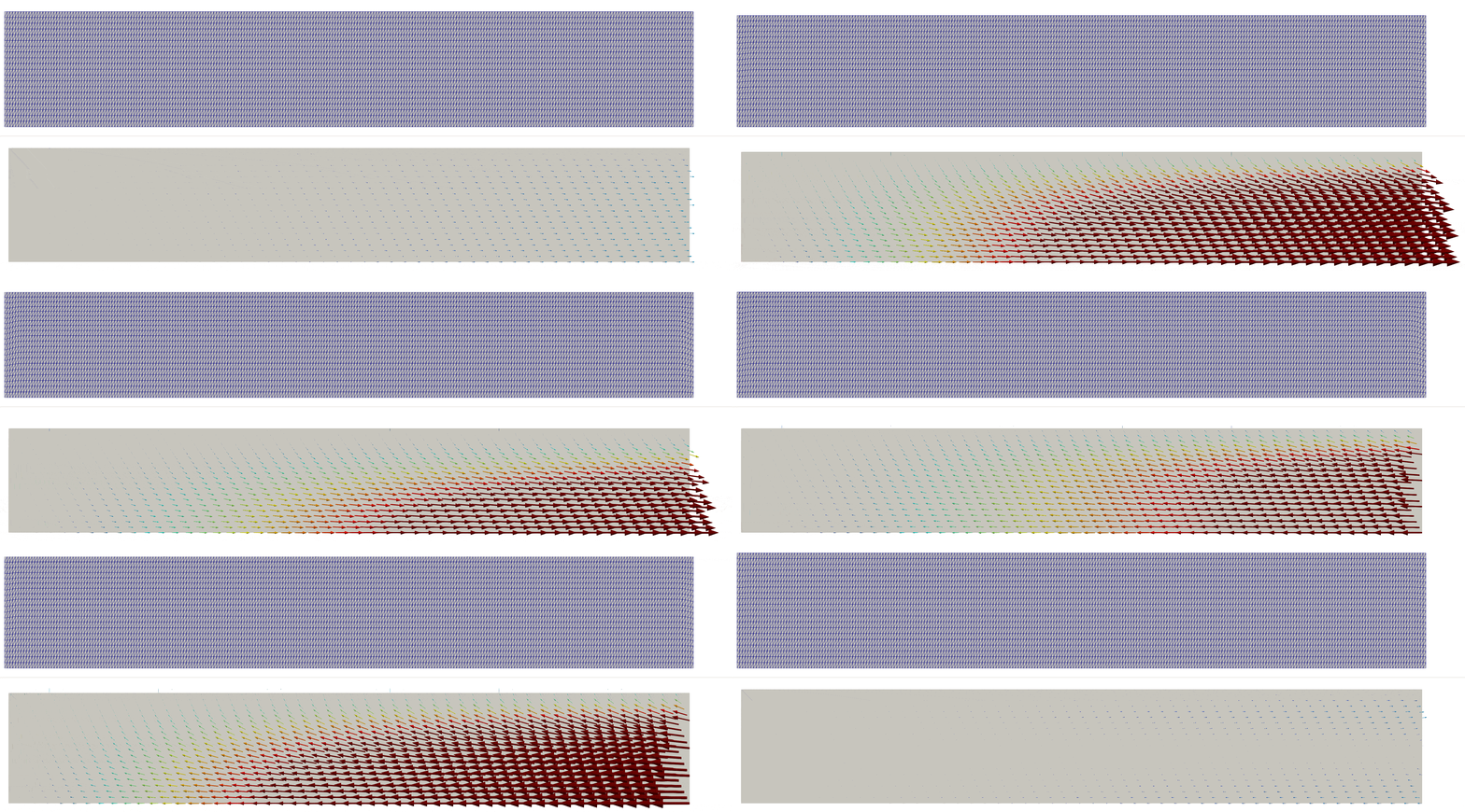
any similar visualization software, and in Fig. 1 we display the displaced grid, and velocity solution over
one period. Note that the solution has been transformed by scaling the length in the \(x\)-direciton by 1/4th.

Fig. 1 On top, the grid displacement, and on the bottom, the velocity field for the wall-driven channel flow, where the vector arrows have been scaled by the velocity magnitude.#
- Chn14
Christophe Chnafa. Using image-based large-eddy simulations to investigate the intracardiac flow and its turbulent nature. PhD thesis, Université Montpellier II-Sciences et Techniques du Languedoc, 2014.
- Nic02
F Nicoud. Hemodynamic changes induced by stenting in elastic arteries. Center for turbulence research annual research biefs, 2002.
