Pre-processing#
Since pre-processing part of VaSP is based on VaMPy, overlapping functionality of the pre-processing will not be covered here. Instead, users are encouraged to refer to the VaMPy documentation for some of the basic functionalities used in VaSP. In this document, we will focus on the newly implemented parts of the pre-processing that are specific for performing fluid-structure interaction (FSI) simulations.
The main script for running pre-processing is preprocessing.py located under src/vasp/preprocessing and can be run by using the command vasp-generate-mesh. Although there are quite many parameters for vasp-generate-mesh, it is not necessary to specify all the arguments. In fact, it is recommended that the user starts from providing minimally required arguments first, and then control the other arguments based on the user’s need for meshing. To run the pre-processing, i.e. generating the volume mesh for FSI simulations, it is required to provide the surface mesh in vtp or stl format. Assume that the user has the surface mesh named my_mesh.vtp. Then, pre-processing can be performed as
vasp-generate-mesh --input-model /[some_path]/my_mesh.vtp
which should produce the following files in the same folder as my_mesh.vtp
my_mesh.h5: input mesh for FSI simulationmy_mesh.vtu: default output mesh file from VMTKmy_mesh.xmlormy_mesh.xml.gz(compressed or not): FEniCS compatible version of the mesh, not used in VaSPmy_mesh_edge_length.h5/xmdf: averaged edge length for each cells. This can be used to check the quality of the meshmy_mesh_boundaries.pvd/vtu: boundary mesh with IDs for each boundaries.my_mesh_domains.pvd/vtu: volume mesh with IDs for each domains.
Among the files generated after pre-processing, my_mesh.h5 will be used as an input to the FSI simulation. However, .h5 file cannot be viewed by Paraview, and thus we have added other files such as my_mesh_boundaries.pvd and my_mesh_domains.pvd for viewing the mesh and IDs with Paraview.
For checking the parameters, please run the following command to get the description of the parameters
vasp-generate-mesh --help
Fluid and Solid mesh generation#
To perform FSI simulations, fluid and solid regions need to be generated and marked so that different partial differential equations can be solved on each domain. In VaSP, the provided surface mesh will represent the interface of the fluid and solid domain. Then, fluid mesh is created inside the surface mesh to fill the provided surface mesh while solid mesh is created outside the surface mesh to cover the fluid mesh. This mechanism of generating two different mesh works very well for blood vessels. We extended VMTK, a framework for generating mesh based for image-based vascular modelling, to enable the solid mesh generation by utilizing the functionality of adding boundary layer meshing. Fig. 1 is an example of FSI mesh with fluid and solid regions marked as 1 and 2, respectively.
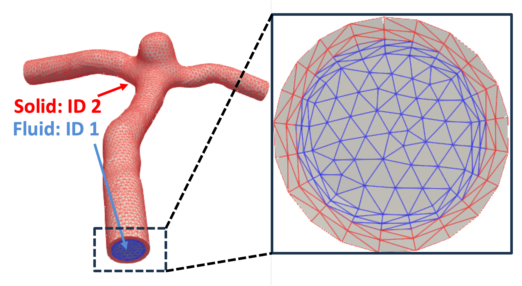
Fig. 1 Fluid and Solid domain with unique IDs#
Boundary IDs#
Similar to the domains, boundaries also need to be marked separately for applying different boundary conditions, as shown in Fig. 2. These boundary IDs can be viewed by opening {your_mesh_name}_boundaries.pvd.
Attention
While most boundary IDs are fixed, fluid inlet and outlet IDs can vary depending on the input mesh.
Therefore, it is necessary to open the {your_mesh_name}_boundaries.pvd and visually check those IDs.
Below is a list of boundaries that are necessary to be identified for performing FSI simulations.
- Fluid inlet
- Fluid outlet
- Fluid and Solid interface
- Solid inlet & outlet
- Solid outer wall
The first two boundaries are necessary for specifying boundary conditions for the fluid domain. In case of do-nothing boundary condition at the outlet, there is no need to specify the ID for the outlet while the inlet ID is always required to specify the inflow.
The third boundary, fluid and solid interface, is required to distinguish static and dynamic boundary between fluid and solid.
The fourth boundary is usually used to fix the solid inlet and outlet while the last boundary is used to specify Robin boundary condition at the outer wall of the vascular system for representing surrounding environment.
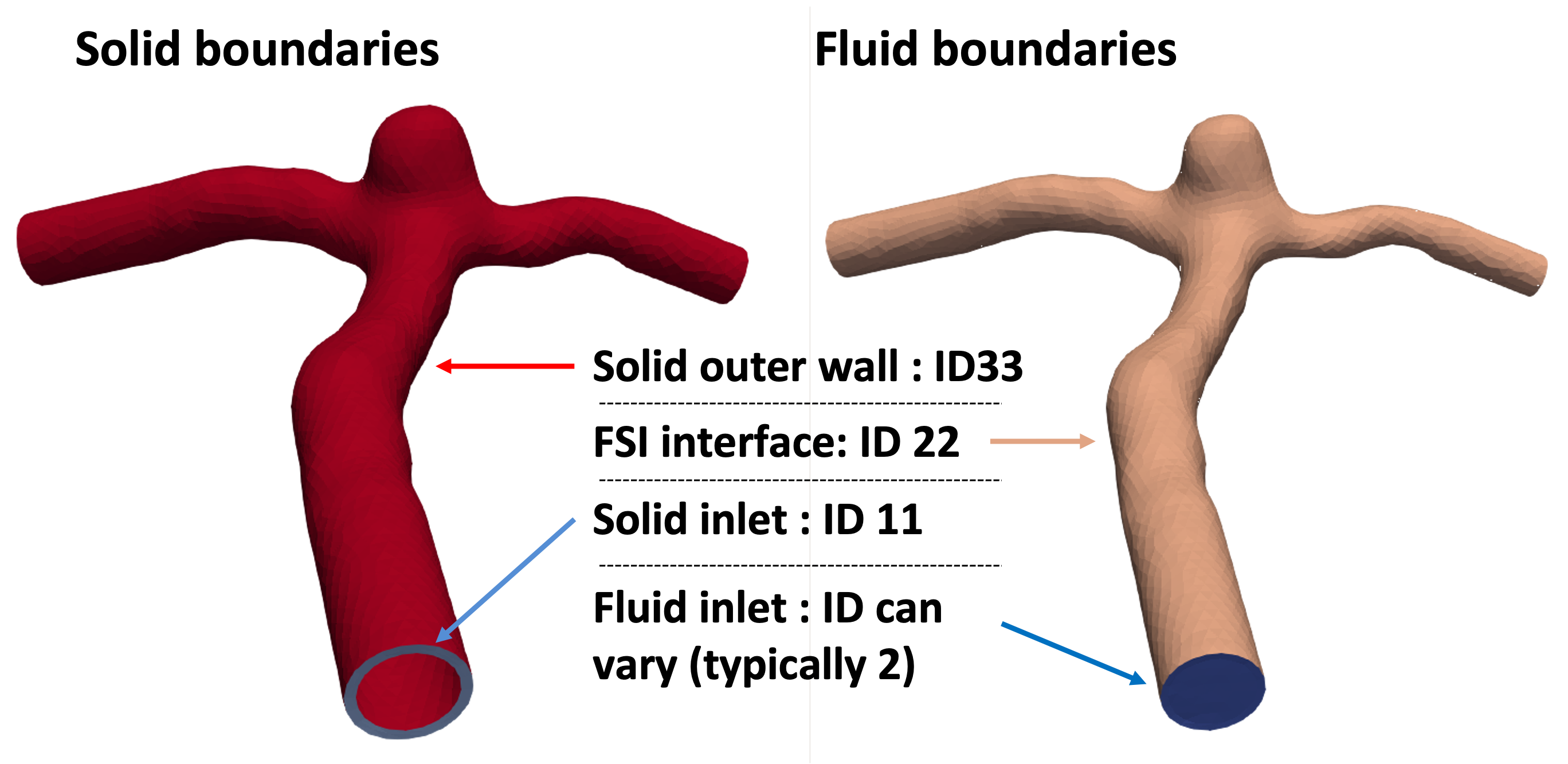
Fig. 2 Boundaries with unique IDs#